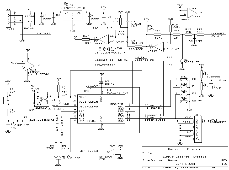
Build your own FRED step-by-step

Deutsche Version  FREMO Contents   FREMODCC   Loconet self-construction   FRED   

Here you will find all steps to build your own FRED: from components to operational device.

Content

  1. Assembly
  2. Test
  3. Commissioning
    3.1 Test program
    3.2 Calibration
  4. Final test
  5. Links

1. Assembly

First you need to obtain all necessary components. Part list and hardware schematics version 1.0  can be found herer:
Mathias Hellmann wrote an excellent instruction manual describing the assembly step-by-step:

2. Test

First of all a request: please check carefully all soldering points! You can't think about how many FREDs didn't work correctly caused by forgotten soldering.
Most of FREDs basic functions can be proved with a test program that you can download into the microcontroller of your FRED. Even a non-technician can ascertain the FRED to do at least anything. All you need is a Loconet capable central unit (Chief, Intellibox, PCU, Frankenzentrale).

If you cannot put your FRED into operation by yourself, it could be wise to ask someone else to download the test program into your FREDs microcontroller before you start assembling. If your FRED finally has been assembled and you have a microcontroller with the test program installed in the socket, your FRED will start a rampant flashing as soon as it is connected to a central unit. The diagnostic protocol will help you to understand the meaning.

3. Commissioning

Here we will meet everybody who knows to use a soldering station and doesn't fear SMD components.  If you don't have the heart to commission your FRED, you can contact the following people:
  1. Heiko Herholz
  2. Eric Hersberger
  3. Thomas Michael Müller
  4. Bernd Wisotzki
  5. Udo Rychly
  6. Heijo Reinl
  7. Jens Schmidt
  8. Jens Emmermann
  9. Jochen Leisner
  10. Dirkjan Kaper
  11. Stefan Haack
  12. Armin Mühl
  13. Stefan Bormann
more people will be added on request.

3.1 Test programm

At first (if not done so far) the test program has to be downloaded into the microcontroller. The microcontroller carries a flash memory that allows to change the program as often as you like. For the programming process you need a piece of hardware interconnected between the serial port of your PC and your FREDs programming socket. During this procedure the FRED must NOT be connected to the Loconet. On the PC run the DOS program "FCalib" provided by Martin Pischky.
As soon as the test program is stored in the FRED disconnect the programming hardware and connect to Loconet. In addition to the central unit a "Loconet Monitor" must be connected to this Loconet. This is a PC, a Loconet Interface (MS-100 or MS-SH) connected to one serial port of the PC and to the Loconet and a running monitoring software (for example LNMON by Martin Pischky). When you plug your FREDs into Loconet the test program will check its hardware. The first message, that must appear on the Loconet-Monitor, will provide the measured CD-time (carrier detect time). This should be close to 1.0 ms. If necessary change the resistor R8 with a different value. Or modify ist: Subsequently the test program will continuously check the resistance of the potentiometer and signal to the Loconet. If you press or release one of the buttons this will also generate a message to the Loconet.
More precise information to fix errors can be found in the Diagnostic Protocol mentioned above.
Caution: don't expect miracles from the test program. As a matter of principle it cannot find EVERY error. Thus an optical check-up of your hardware is mandatory. Is every part in its place? Can you trust all your soldering points?

3.2 Calibration / FRED-ID

Not all resistor values are exactly the same in every FRED because of tolerances. Therefore two correcting values must be written to your FRED to use the full range of the potentiometer.
Turn the potentiometer to its leftmost and its rightmost position. Record the lowest and highest values shown on the Loconet-Monitor. Enter these values into the relevant input fields in FCalib. FCalib will now calculate the calibration values (Offset and Factor).
In addition every FRED needs to get a unique identifier. This identifier is assigned and registered centrally:
Now that calibration values and FRED-ID are certain and entered into FCalib. Disconnect the FRED from Loconet  and re-connect with the programming adapter. Now request the program to download these values into the microcontrollers memory. Finally download the actual FRED program into the microcontrollers memory.

4. Final test

Connect your FRED via Loconet to a central unit and a Loconet-Monitor. At DT100 or Intellibox  release a loco. This loco will be taken over by the FRED. Now observe the Loconet-Monitor. Right most position of the potentiometer must be speed step 127. Left most position must be speed step 0. Each button and the direction switch must send a message on Loconet. Finally don't forget to de-select the loco: a free available FRED will always be taken to meetings without a loco ID!

5. additional Links

Deutsche Version  FREMO Inhalt   FREMODCC   Loconet self-construction   FRED   

Author of this page: Stefan Bormann.
Translation: Christian Valder
URL: http://fremodcc.sf.net/diy/fred/aufbau_e.html
SourceForge.net Logo